TCP & UDP, or the two pillars of the Internet
Last edited:
As a company that offers a CDN service, we know a lot about this technology. In this series of articles, we’re trying to describe how a CDN works and what the things that make the existence of CDN possible are.
In the previous article we discussed the structure of the Internet, the differences between mediums, and the problems that users encounter trying to connect to servers far away from them. Now it’s time to go a few levels up to see what is “the language” computers use to communicate with each other.
The plan
There is no way we can even briefly discuss everything that relates to the Internet. Thus, in this and the following articles we are going to look at the exact subset of the technologies — the part laying between physical connection and applications.
We’re not going to discuss how computers use electricity to represent and transfer data. This topic is fascinating, but it is too low-level for us.
At the same time, we won’t discuss in detail how your browser loads pages: no HTTP requests, no compression, no programming languages evaluation, and no rendering.
What we are going to discuss is how the data from your computer finds its way to another computer.
Switching
If you’re old enough, you might remember the landlines we had back in the days at home. Or maybe you still have one! If so, you probably know that a hundred years ago they worked in a semi-manual mode.
First, you had to ask a switchboard operator (who was a real human) to connect you with your friend from another city. The operator said “OK,” hung up, and then later they called you back with your friend “on line.”
What you may not know is the procedure this operator had to do for you. They switched cables from one port to another to create the connection:
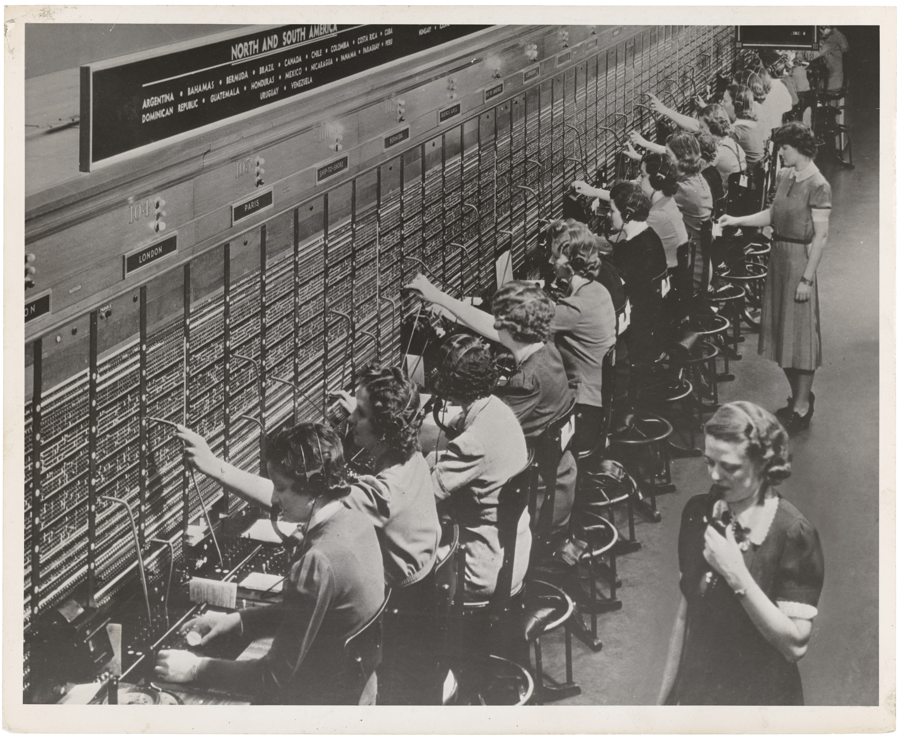 A Bell System switchboard where overseas calls are handled. December 22nd, 1943
This operation is called circuit switching. Circuit switching is a method of establishing a connection between two nodes of a network when they have a dedicated channel to communicate through. It means that when you dial a friend, there is someone or something that literally builds up a cable path from you to your friend.
As you might guess, this type of commutation does not suit the Internet well, because we connect all the time to servers all over the world. Implementing physical cable switching for this purpose would be too crazy. It would be too expensive to create and even more expensive to maintain.
Instead, the Internet is built upon packet switching. In this type of communication, there is no physical cable switching. When we send a message from our computer to our friend’s computer, it goes through different networks, each of those transferring the message to the path that it thinks would be the best.
This may sound mad, but most of the time there is no “main coordinator” of the Internet who decides where every packet must go. Our computer simply “throws” the packet to the network, and all the devices in this network are trying to decide where this packet should travel. Surprisingly, almost all the time these devices do their job pretty well. All thanks to the protocols!
Protocols
A protocol is a set of rules defined to allow nodes of a network to transmit data properly. You probably know some high-level protocols such as HTTP, SSH, IMAP and DHCP.
There are tons of protocols in the communication area that are used for different purposes. Due to the huge amount, there are even special models defining “layers of protocols.” We might imagine these layers as a collection of different candy wrappers.
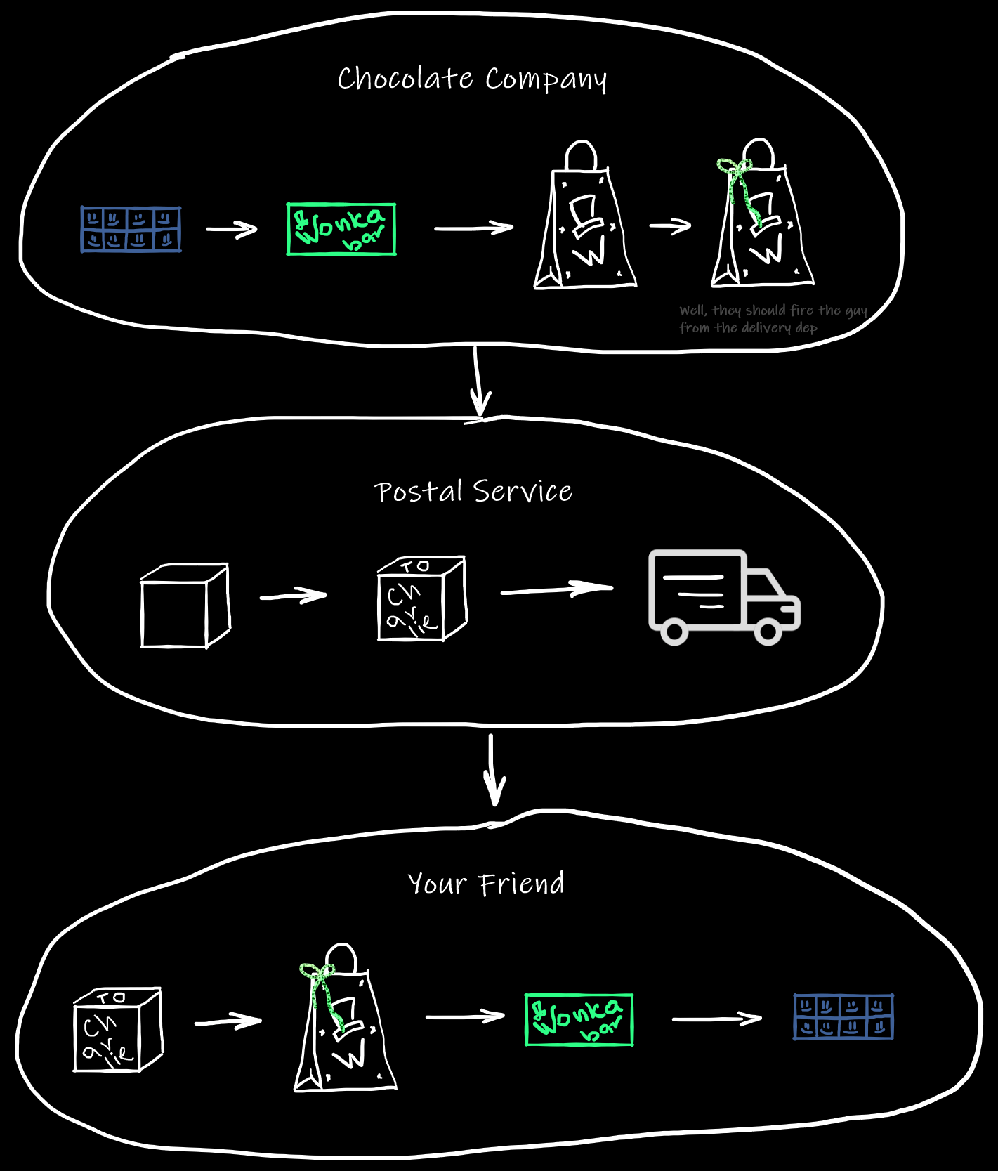
Let’s say you have ordered a bag of delicious handmade chocolate from a local manufacturer to make a gift for your friend.
First, a cook wraps a chocolate bar with its wrapper. Then a packer put the bar into a branded bag. After that, somebody from the delivery department uses a piece of wrapping paper to make it look like a gift. Finally, they pass the gift to the postal service.
When the postal service gets the gift, they put it into a box and write the address of your friend on this box. Then they load a truck with the boxes like yours and go to deliver.
The process goes vice versa on your friend’s side.
This wrapping on each step is literally how protocols work on the Internet:
 Except, it’s much more complicated than wrapping chocolate bars.
OSI & TCP/IP history
Historically there are two main models describing protocol layers. One of them is theoretical — the OSI model and another is practical — TCP/IP model.
There were a lot of possibilities and a lot of problems to solve in the telecommunication area in the 70-80s. There was no Internet as a thing, but there were a bunch of networks created by different companies. Those networks needed a common language to communicate. Therefore many people wanted to create this language. Roughly speaking these people were split into two groups.
The first group believed that the development of the language should be an open process, with all the criticism discussed and all the issues resolved. This group named the standard they were trying to create — OSI, standing for Open Systems Interconnection.
Another group chose a different way, they started to develop and test protocols on the network they already had. Thereby, they created TCP — Transmission Control Protocol, and IP — Internet Protocol. Initially, these protocols were the parts of one big protocol, but later they were divided into two to take the maintenance easier.
This group successfully tested and moved the network they had to this TCP/IP stack. This happened on January 1st, 1983. This is truly the day when the Internet was born.
After that TCP/IP started to gain popularity because it simply worked. Also, it was a free-of-charge model, while authors of OSI wanted to get money for each usage of their standards.
So, what happened with OSI? The initiative failed. Due to the idea of “openness”, the people, who made decisions back then, spent a lot of time in discussions and disputes. Some of these people tried to lobby for ideas that were beneficial to large corporations. Others forced everybody to discuss small, not important things.
Even though the OSI model didn’t find its way to the real world, it’s still used as a good theoretical model of protocol layers. But the model that is implemented is TCP/IP.
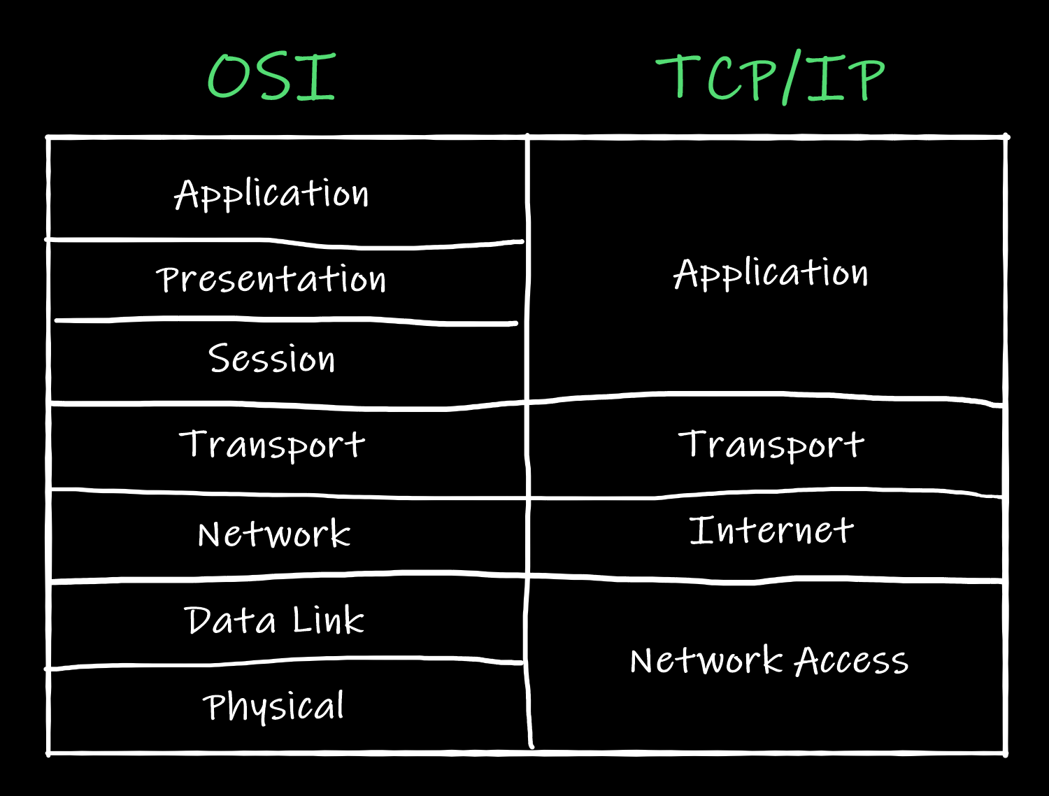
Here’s how the layers of the models look:
TCP/IP
Usually, when people discuss OSI and TCP/IP they try to compare these models and match their layers. Even though the pic above looks like a comparison, we are not going to compare the models, because layer matching is not so important. Even more, the layering itself is “considered harmful” according to RFC 3439.
The key protocols of TCP/IP are obviously TCP and IP. Everything around them is not so smooth, so even authors of textbooks about network communication cannot agree with each other about the exact number of layers or their names.
Is there a Physical Layer below the Network Access Layer? Should we even call it Network Access Layer, or it’s better to call it Link Layer? There are many questions like these. However, all of these questions do not matter, because the main idea of the TCP/IP stack is pretty simple.
Let’s say two applications on the network want to communicate. One of them generates a message. This message may be formatted using a protocol like HTTP, or not, it does not matter. The message is generated on the Application Layer.

This message is passed to the Transport Layer, where it’s prepended with a TCP or a UDP header. The header contains information about the ports those applications are using and some other important information which we will describe later. The result of this prepending may be called a datagram or a segment.

Then, the segment is passed to the Internet Layer. It’s pretended with an IP header, which contains the addresses of the computers that run the communicating applications. The combination of a segment and an IP header is usually called a packet.
There is no big difference between datagrams, segments and packets. Most of the time all of them are called “packets.” The terms “datagram” and “segment” are used when it’s important to highlight the type of the protocol handling the entity.
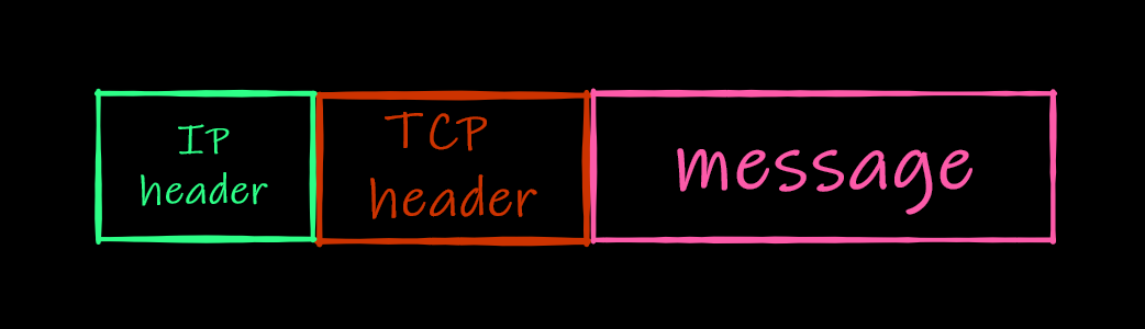
Finally, the packet is passed to the Link Layer, where it’s encoded and transmitted over the network. There are protocols on this level that also add their headers to each packet, and the result of this addition is a frame.
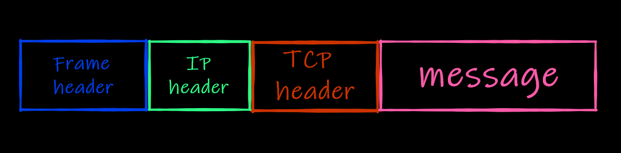
Frames usually contain not only the header but also the footer. E.g. here’s what an Ethernet frame for our message may look like:
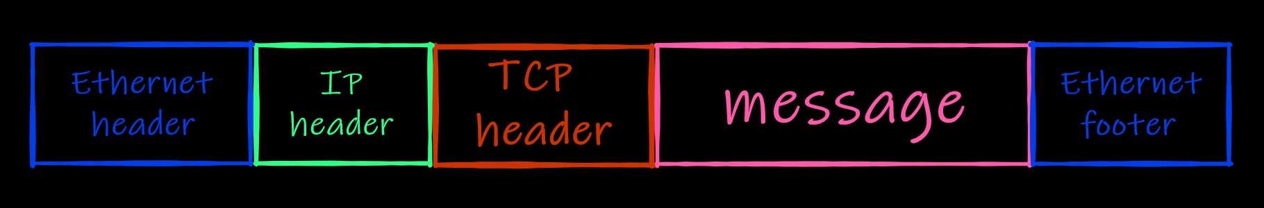 The scale of the scheme is not real, of course. In reality message is much bigger than the headers & the footers
When the frame is passed from one intermediate node to another during the communication, these nodes disassemble the frame, check the packet’s header, decide what they should do with the packet, then create a new frame for the packet and pass it to the next node.
So, when the message is passed through nodes like this:
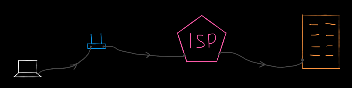 If you haven’t read the previous article, then know that the last orange rectangle is a Google server. The author of this article is definitely an artist
The underlying data flow looks like this:
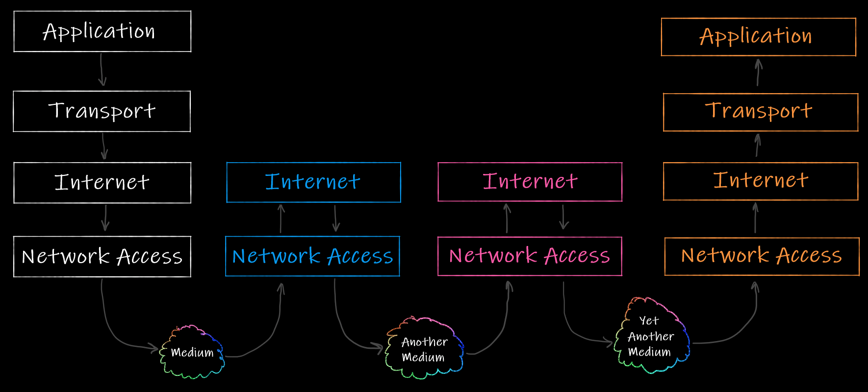 At the start and at the end of the packet path all the TCP/IP layers are involved, while the intermediate nodes use only Internet and Network Access layers
Alright, now we know that TCP/IP specifies the protocols of the Transport and Internet Layers, but does not care about the protocols of the Application and Link Layers. Let’s see what’s going on on the Transport layer in detail.
TCP & UDP
The Transport Layer of TCP/IP stands on two main protocols: Transmission Control Protocol and User Datagram Protocol. There are other protocols on this layer (e.g. QUIC) but they are not so commonly used yet.
The protocols of the Transport Layer are used to address the packet from the source port to the destination port. Moreover, the protocols do not know about the differences between nodes on the used network. Everything the protocols know about addressing is the fact that the source application is bound to a port, and the destination application is also bound to a port. The actual “Internet addressing” is done by Internet Protocol which we will describe in the next article.
UDP is much “lighter” and simpler than TCP, but at the same time, UDP is not reliable and does not do much work compared to TCP. To see the difference between these protocols, let’s start with the User Datagram Protocol.
User Datagram Protocol
This protocol is used for “connectionless communication,” which means that the connection is not set up before the actual sending. One node sends packets to the network addressing them to another node. The sender node does not ensure that the recipient node exists or is ready to receive the packets. The sender node also does not wait for confirmation that the recipient node has got the previous packets.
The packets handled by UDP are sometimes called datagrams. The term usually describes the packets sent using any connectionless communication.
UDP header contains 8 bytes of information that includes:
- Source port
- Destination port
- Length
- Checksum
As simple as it sounds. A typical UDP datagram looks like this:
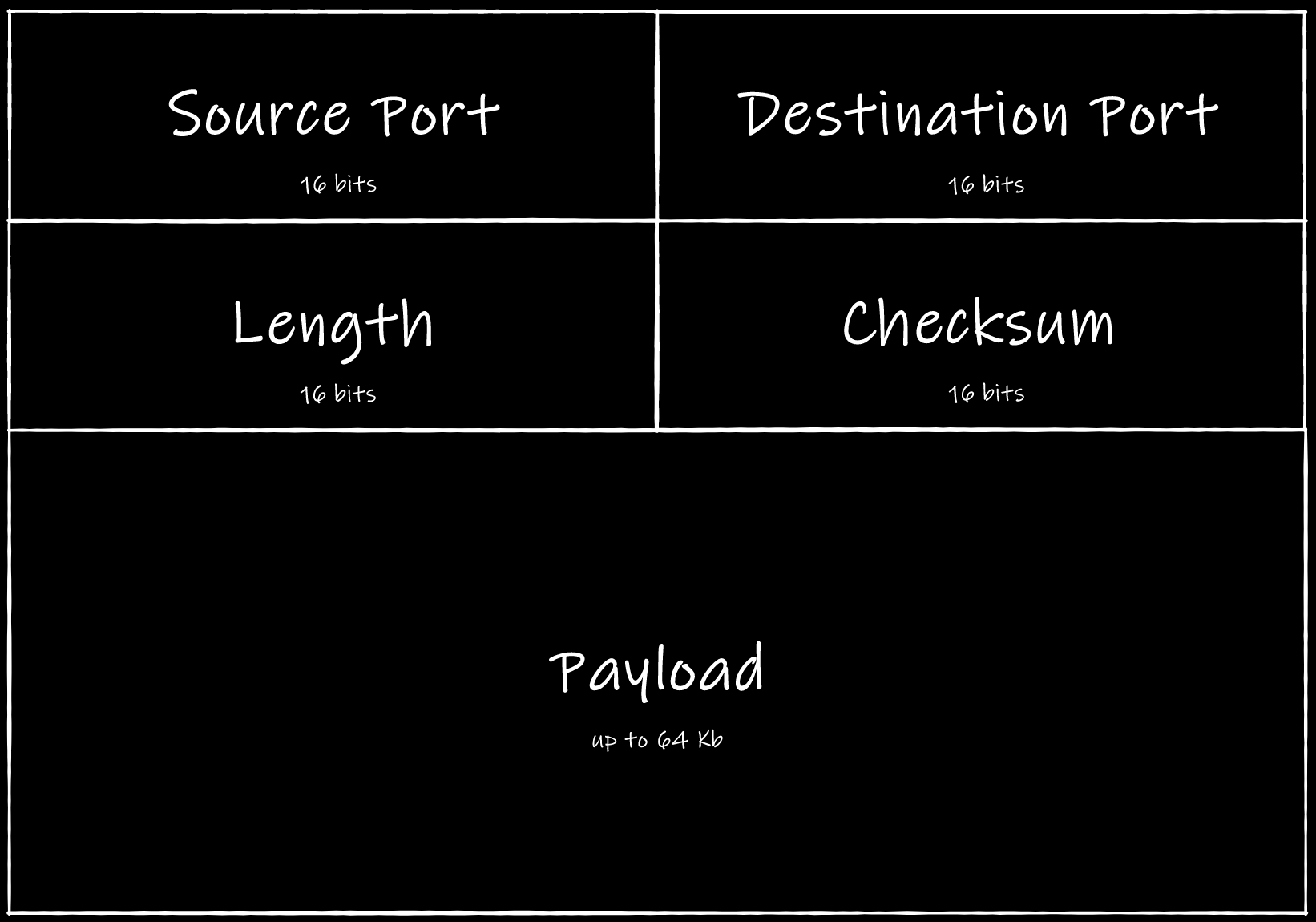 Payload is a message the datagram carrying to the recipient
Field test
It’s easy to set up a UDP server on your own. Here is an example written in Node.js right from the official docs:
const dgram = require('dgram');
const server = dgram.createSocket('udp4');

server.on('error', (err) => {
  console.log(`error:\n${err.stack}`);
  server.close();
});

server.on('message', (msg, rinfo) => {
  console.log(`got a message from ${rinfo.address}:${rinfo.port}: ${msg}`);
});

server.on('listening', () => {
  const address = server.address();
  console.log(`listening ${address.address}:${address.port}`);
});

server.bind(8082);
Let’s start the server:
$ node udp.js
server listening 0.0.0.0:8082
Now we can use netcat to send datagrams from another terminal window:
$ nc -u 127.0.0.1 8082
Hello, server!
Do you have a minute to talk about UDP?
Our server successfully handles the datagrams we’ve sent:
$ node udp.js
server listening 0.0.0.0:8082
server got a message from 127.0.0.1:55823: Hello, reader!

server got a message from 127.0.0.1:55823: Do you have a minute to talk about UDP?
As you see netcat has bound itself to the port 55823 to send the packets. If we use Wireshark to intercept the packets, we will see this:
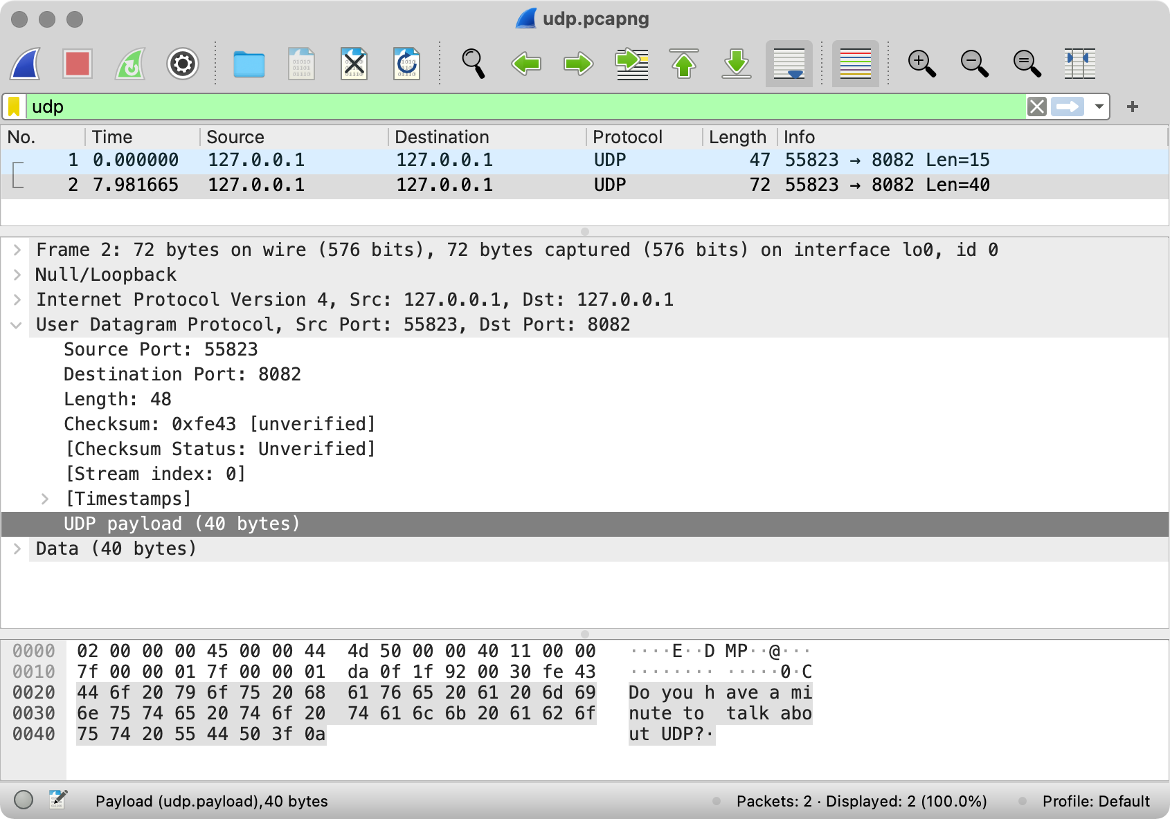 Quick Wireshark tutorial. At the top, there is a log of the packets. Below there is parsed data of the chosen packet. Note that all the data surrounded by square brackets is calculated by Wireshark and does not exist in the packet “as is”. Finally, at the bottom, there is a text representation of the packet.
By the way, if you don’t want to set up a Node.js server and capture the communication yourself, feel free to use our dump file.
So, what do we see here? The source port is 55823 as netcat picked. The destination port is 8082 as we set it. The length is 48 bytes because the first 8 bytes are occupied by the header and the rest is the message we sent. Finally, there is even some checksum set by netcat.
As you see, there is no answer from the UDP server in the Wireshark log, so the client can’t be sure that the server actually got the datagrams. That’s why UDP is used when it’s fine to lose messages, e.g. for video or audio streaming. It’s possible to use TCP for these purposes, but as you will see in a moment the usage of TCP slows down media streaming.
Well, UDP does not have confirmations but we still can detect unreachable destinations using ICMP. Try to send UDP requests using netcat without the started server and check the Wireshark logs. Here’s what you may see there; here’s the dump.
Transmission Control Protocol
While UDP is simple and connectionless, TCP is complex and connection-oriented. It means that before sending the data, the client and the server establish the connection — they agree on some sort of settings they will use to communicate.
Unlike datagrams in UDP, packets handled by TCP are called segments.
Here’s what TCP does during communication:
- It ensures the order of the packets.
- It ensures delivery.
- It controls the flow of packets to avoid network nodes’ congestion.
That’s a lot of work, so the TCP header’s size is at least 20 bytes. The header includes:
- Source port
- Destination port
- Sequence number
- Acknowledgment number
- Header length (or “Data offset”)
- 9 control bits (or “Flags”)
- Window size
- Checksum
- Urgent pointer
- Options
Here’s a picture to visualize the segment:
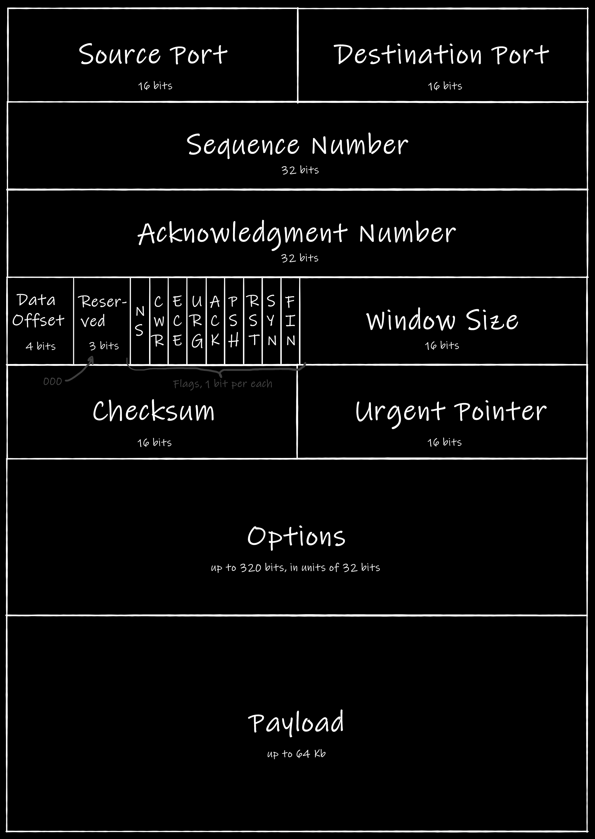 The size of the options fields are dynamic
The source port, the destination port and the checksum are the same as in the UDP header. To explain the purpose of the rest header fields let’s create a test server.
Field test
Let’s set up a simple TCP server using Node.js (again, using the code from the official docs):
const net = require('net');

const server = net.createServer(connection => {
  console.log('client connected');

  connection.on('end', () => {
    console.log('client disconnected');
  });

  connection.write('Hello, client!\n');

  // 'connection' is a stream which we can pipe

  // first we pipe to stdout to print messages from the client
  connection.pipe(process.stdout);

  // then we pipe to itself to force this stream to read itself
  // making the incoming messages outcoming
  connection.pipe(connection);
});

server.on('error', (err) => {
  console.log(`server error:\n${err.stack}`);
  server.close();
});

server.listen(8082, () => {
  const address = server.address();
  console.log(`server listening ${address.address}:${address.port}`);
});
The code above looks like the UDP server we created earlier, but instead of straightforward handling of incoming messages, we operate a connection object. This connection object allows us not only to print the messages we get, but also to detect when a client is connecting or disconnecting, and to send some responses back. If you set up HTTP servers earlier you should see the similarities.
Let’s start the server using this code:
$ node tcp.js
server listening :::8082
A double colon instead of a “usual” IP means that the server is bound to the localhost using IPv6, but it does not matter for now.
Now use netcat to start a TCP connection to the server from another terminal window:
$ nc 127.0.0.1 8082
Hello, client!
The string we’ve got here has come from the server when the connection has been successfully established. Here’s what we have in the server logs:
$ node tcp.js
server listening :::8082
client connected
As you see the server got a notification from the client and it knows that the client exists, and this client is going to send something. So let’s send:
$ nc 127.0.0.1 8082
Hello, client! # message from the server
Hello, server! # our message
Hello, server! # reply from the server
Hey, stop it!  # our message
Hey, stop it!  # reply from the server
We’ve written a simple echo server, which sends back everything it gets from us.
Close netcat by pressing Ctrl+C and check the server logs:
$ node tcp.js
server listening :::8082
client connected
Hello, server!
Hey, stop it!
client disconnected
There are two messages we sent earlier and the notification about the disconnection.
So, how is it possible for the server to know about the connection state while we haven’t sent anything yet? To figure it out let’s use Wireshark again.
Here’s how all the connection looks there:
 Much more than in the UDP version
Again, if you can’t set up a Node.js server by yourself, but want to dive into the logs, feel free to use our dump.
That’s a lot! Let’s investigate!
Handshake
When a client wants to send data to a server, first they both should establish a connection. This “establishing” is usually called handshaking.
The handshake consists of three steps:
- A client sends a packet called SYN to the server.
- The server sends a packet called SYN-ACK to the client.
- The client sends a packet called ACK to the server.
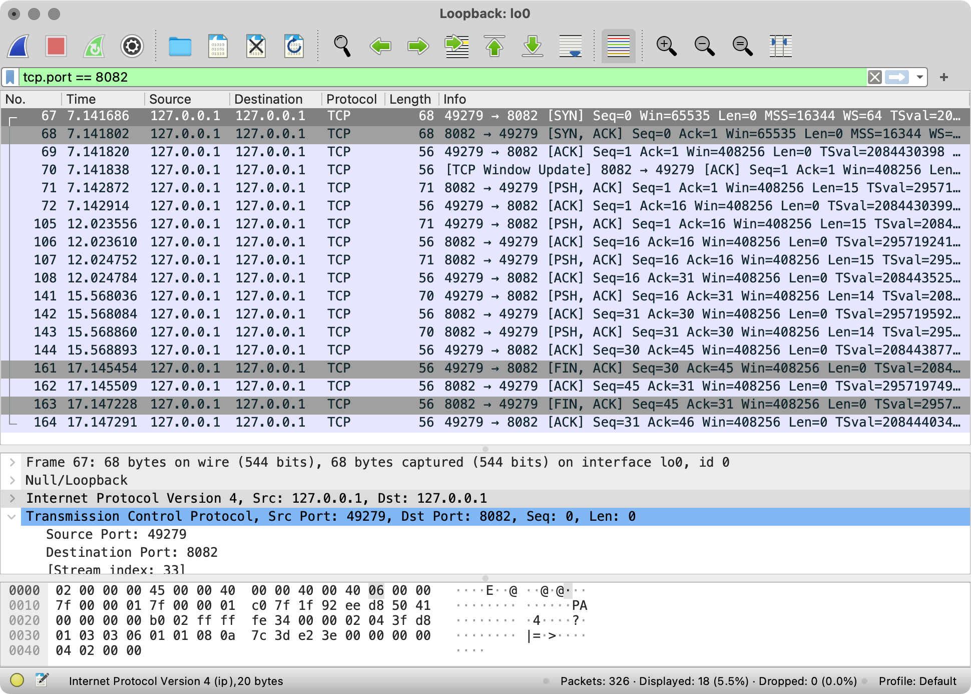
The names are derived from the flags that are set in the TCP headers of these packets. Here’s how the first packet looks in Wireshark:
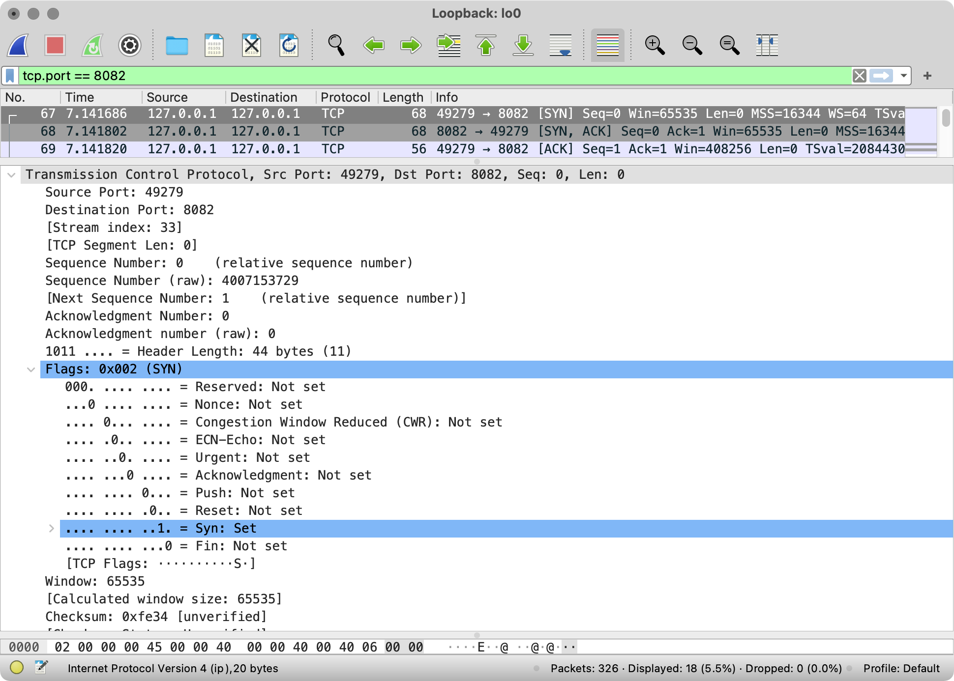 SYN flag is set
As you see, one of the bit flags is set to 1. This flag is called “Syn,” standing for “Synchronization”.
TCP is a reliable protocol, which means that the sender is always notified whether or not the recipient has got the packet. To implement this feature TCP specifies special types of packets (such as SYN, ACK, etc) and every TCP header contains two numbers: Sequence number and Acknowledgment number.
The sequence number refers to the amount of data that the sender of the packet has sent so far. The sequence number is increased by 1 when SYN or FIN flags are set, it’s also increased by the payload size when the payload exists. The number does not include the current packet. Thus, the first packet sent by the client always has a sequence number set to 0.
The acknowledgment number refers to the amount of data that the sender of the packer has received for far. It’s a mirroring of the sequence number from the opposite side of the connection, but with one step ahead. Thus, the first packet sent by the server has an acknowledgment number set to 1.
Actually, the starting values of those numbers are picked up randomly. But it’s easier to operate on relative values as you may see on the Wireshark screenshot above.
Those numbers are useful because they help to maintain the state of communication on both sides. Both the server and the client expects to get exact acknowledgment and sequence numbers from the other side. When the actual numbers are not the same as expected, it means that there is an error somewhere and someone should retransmit the data.
Here’s how the handshake looks in our case:
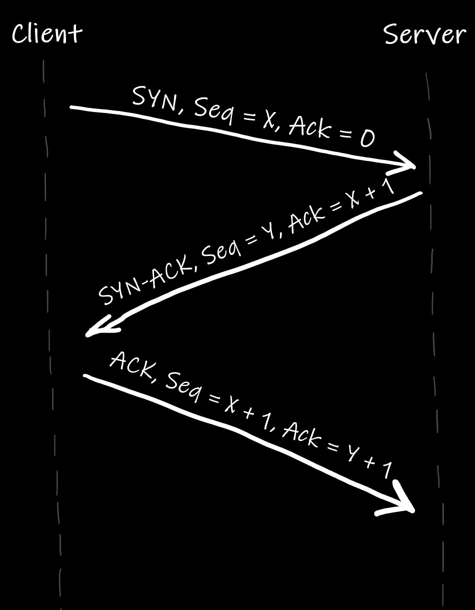 Let’s pretend the vertical lines on this drawing are actually vertical
When the handshake is done, our server knows that there is a client ready to communicate, and the server waits for this communication.
Data transfer
When the handshake is done, it is time to send a payload.
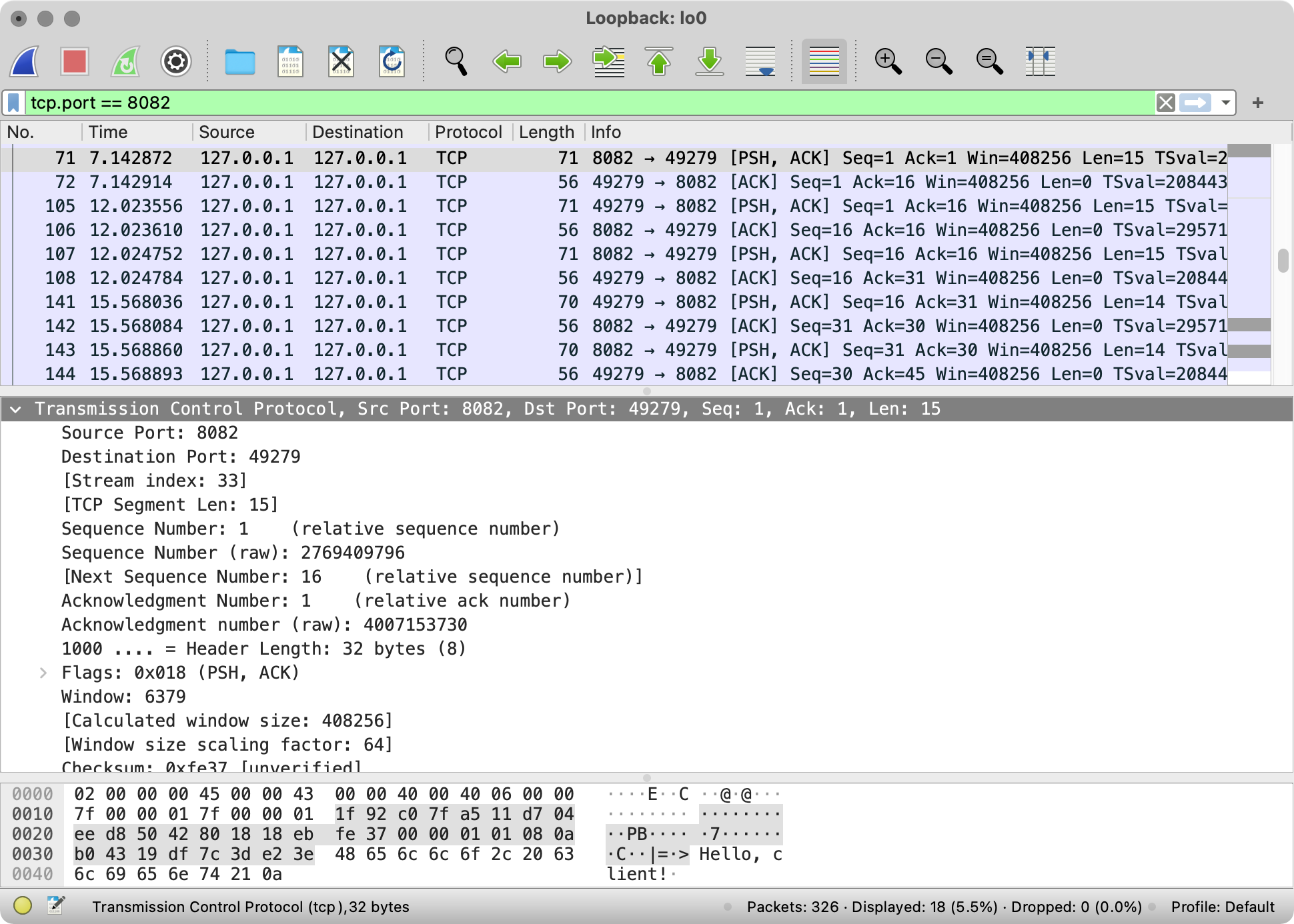 Example of a segment carrying payload in the Wireshark log
As you see in the log above, each piece of information sent by one end is ACK-ed by the other using a separate segment.
It looks straightforward, but that’s because our example is simple. In the real world, there are a lot of problems: packages may be lost, the channel may be congested, an error might occur, and so on. TCP handles all these situations. How? This is a story for another long series of articles. Let us know if you’re interested and we may write about TCP in detail.
By the way, every packet in the log above has the flag PSH set. This is unusual, and in real life, this flag is not so commonly used. This is probably netcat-specific behavior.
Termination
When one of the nodes is going to close the connection, it initiates a termination. The process itself looks similar to the connection initiation, but instead of using the SYN flag, the ends use the FIN flag.
Here is the termination in our Wireshark log:
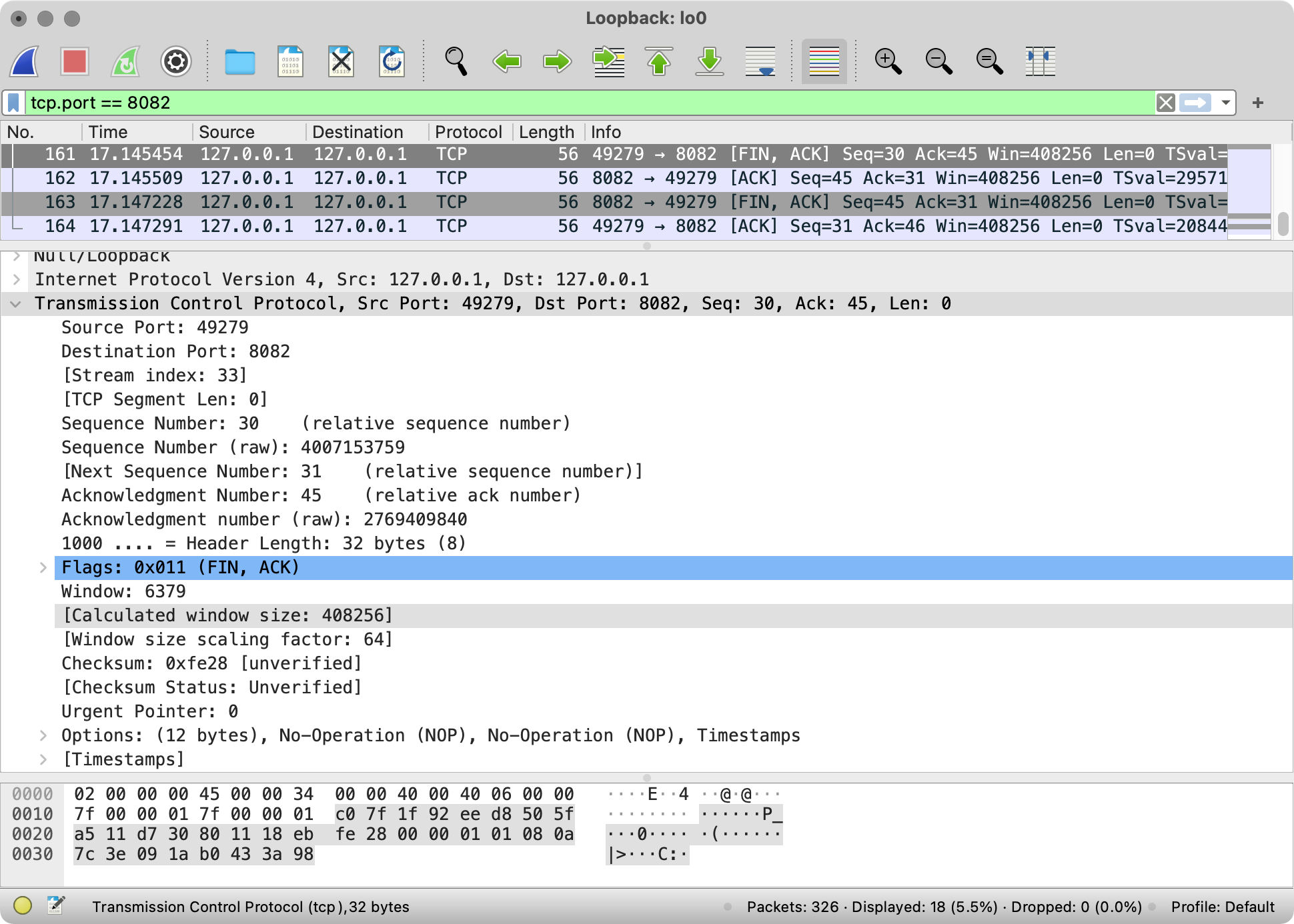 Two pair of FIN-ACK & ACK segments
In our case, the termination has taken four segments, which is not like a handshake. It works this way because when the connection is terminated, the other party (the server in our case) must first notify the Application Layer about the termination. When the app that is using the connection is ready to close it, then the TCP of the other party sends its FIN packet.
Since nodes “agree” on the termination we can listen for such an event in our code above.
By the way, sometimes termination is triggered by the RST flag instead of FIN. It’s kind of hacky, but it is possible. Also, the RST flag is used for the attack which prevents TCP connection between the nodes. If it sounds interesting to you, check out this article by Robert Heaton.
Summary
In this article, we’ve found out that the Internet is built around packet switching, and the core protocol stack is TCP/IP. We have also briefly looked at the two main protocols of the Transport Layer of TCP/IP: the very TCP and UDP.
In the next article, we will dive into Internet Protocol, and we will see how it glues every computer in the world into the biggest network.