Internet addressing
Last edited:
In this series of articles, we’re discussing the tech stack that makes CDNs possible.
In the previous articles we’ve told you about the structure and the history of the Internet, we’ve described the differences between the OSI and TCP/IP stacks, and we’ve looked at the transport protocols, such as TCP and UDP.
Now it’s time to go a bit deeper and look at the protocol standing right behind the transport ones. Let’s dive into Internet Protocol!
Ethernet addressing
Usually, in this series, we go from the top to the bottom of the problem. To discuss mediums we started with the structure of the Internet, to describe TCP and UDP we started with the protocol models.
This time we’ll cover the topic differently — it’s easier.
Let’s imagine that we have two computers and we want to connect them. We might connect the computers using one wire, but it would be great to make our network scalable, so we use a hub to build the network.
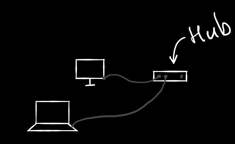 Your home router works like a hub too
The hub does a pretty simple job, it distributes the packets it gets through the network. In our case, we use wires to connect the computers to the hub. Usually in this case the “lowest” protocol that is used for passing information is Ethernet. How does Ethernet work?
Every computer has a Network Interface Controller (NIC). Nowadays, this controller is probably built into the motherboard of your computer, but 5-10 years ago it looked like this:
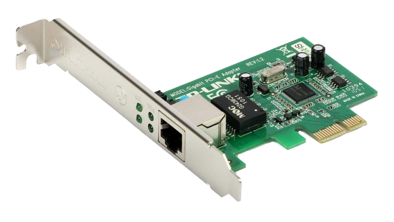 It looks outdated these days; like a thing inside a game cartridge, you know
Each NIC has its own “physical address.” You probably know it under the name MAC address. This address is a 48-bit number which is usually written as 6 hexadecimal numbers split by dashes or colons. You may easily find your NIC’s MAC address in the network settings of your computer.
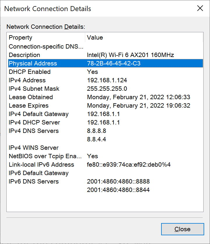 This is how it looks on Windows
Now, imagine that you have a network of wired-up computers. You may send any message to this network, but all the computers will get this message. You need something that will say “This message is for computer #1.” So, MAC address is the thing that Ethernet uses to tell the computers in the local network to which device the Ethernet passes its message.
Ethernet frame’s header among other fields has two related to the addressing: Destination MAC and Source MAC.
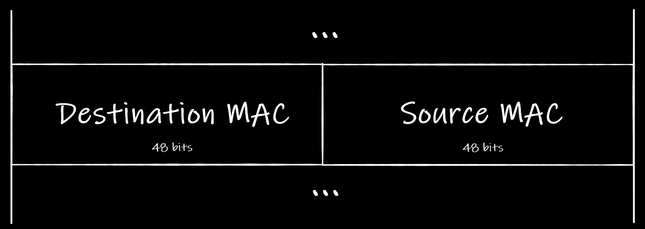 A sneak peak of an Ethernet header
When your computer sends an Ethernet frame to the local network it puts its own physical address into the Source MAC field and the recipient’s address into the Destination MAC field.
That’s how the addressing works in LANs when all the computers are connected to each other using bus lines or hubs.
But what should your computer do if it wants to send a packet to the Internet?
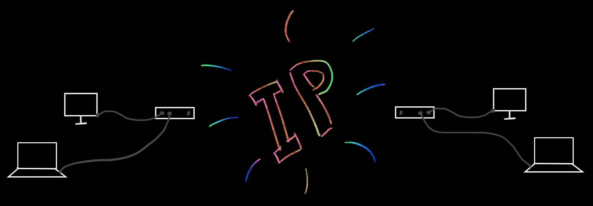
Internet Protocol addressing
“Internet” in the name of this protocol does not mean “the Internet” we all use. “Internet” here means “internetworking.” The thing that this protocol is created for.
To make “internetworking” possible you have to ensure that all the computers in the global network have unique addresses. Otherwise, you won’t be able to distinguish them.
Due to the fact that we’re all programmers here, we decide that the unique number is the best address. So, let’s enumerate all the computers of the network using some big numbers. 4-byte numbers look big enough:
 4-byte unsigned number is something between 0 and 4 294 967 296
But such numbers are not so easy to memorize and write down. To ease the pain we may split each byte of the number by some sign, say, dot!
 Looks familiar, right?
Yeah, IP addresses are just big fancy formatted numbers.
Note: In this article, we’re talking about IPv4 only. IPv6 works in a different way, so not everything that we will describe below is applicable to IPv6.
Now imagine that instead of the hubs we have routers, which are connected somehow, and we really want to send a packet from the computer 192.168.0.2 to the computer 192.168.128.2. Where should we start?
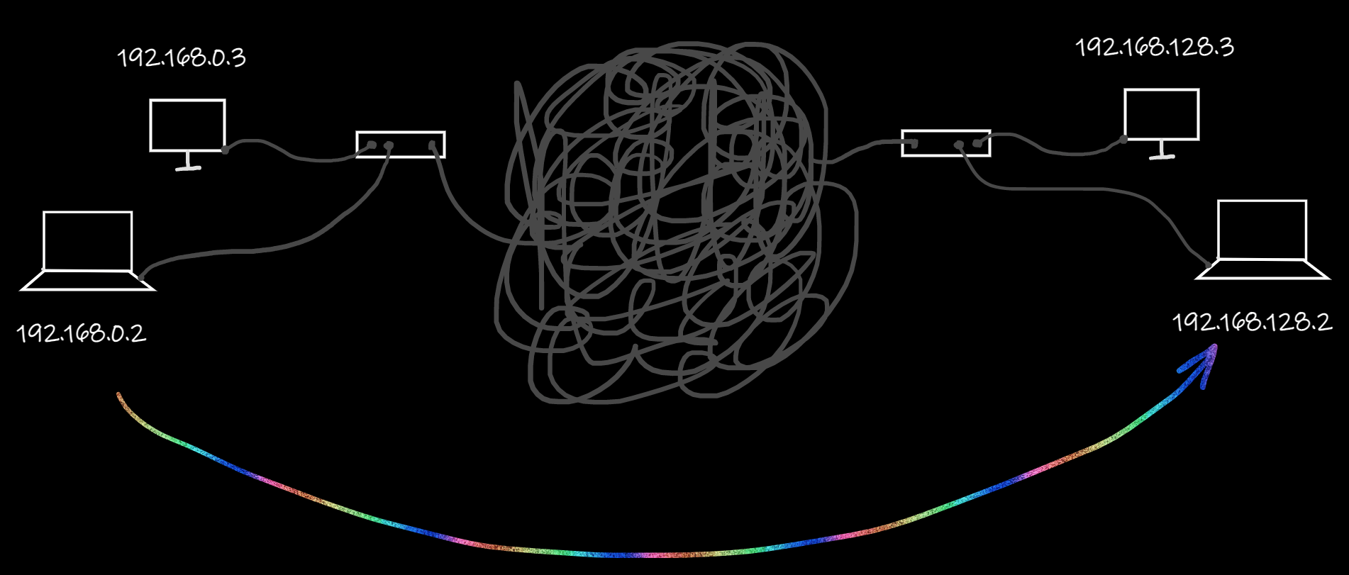
Well, it looks like we should pass the packet to the router and somehow ask it to pass the packet further. As you remember from the previous article, IP packets are wrapped by Ethernet frames. So we may set 192.168.128.2 as a recipient’s address inside the IP packet. At the same time, we may set our router’s MAC address as a destination point inside the Ethernet frame. Thus, the router will get the Ethernet frame, unwrap it, check the IP address inside the IP packet, figure out that there’s no such a computer inside our network, and pass this packet outside our network.
But wait.
How does our computer understand that 192.168.128.2 does not belong to our network? And how does our computer know what machine is a router in our network?
Subnetting
If you have ever set up your home network by yourself then you set three “addresses” in your computer settings: IP Address, Subnet Mask, and Default Gateway. If you haven’t done it, it is fine. Your computer gets them every day from your router using DHCP.
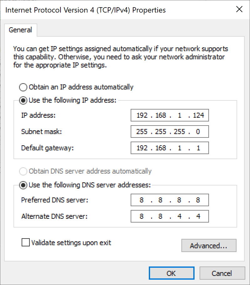 Here you see them set at the top of the form
Default Gateway here is the IP address of your router. The Subnet Mask is more interesting though.
Let’s say your computer knows its own IP address (e.g. 192.168.0.2) and the one the router has (e.g. 192.168.0.1). What should the computer do to find out other possible IP addresses of your local network?
Well, years ago, at the dawn of the Internet, the way to determine whether an IP address was “local” or “external” was pretty simple. The whole Internet was split into smaller networks using the first octet of the IP address. If the first number of your IP address does not equal the first number of your friend’s IP address, then you’re using different networks.
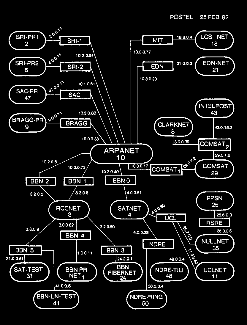 Map of the prototype Internet in 1982, showing 8-bit-numbered networks (ovals) only, interconnected by routers (rectangles)
But that way to split the Internet wasn’t the best, because only 256 networks were possible to create. So the researchers who were trying to solve this problem came up with a solution. They decided to split the Internet into networks of different sizes. The sizes themselves were called “classes”. So, there was Class A, Class B, Class C, and so on.
We are not going to break down the way of splitting. If you wish, you can read about classful networks on Wikipedia. What’s important here is that this splitting didn’t help. Yeah, it was cool that we had more isolated networks inside the Internet, but the classes were not great. Any class A network contained 16+ billion addresses, class B — 65+ thousand, class C — 256 addresses. What should a company that wants to get 300 addresses do? Well, nothing else but getting a class B network. This means that more than 99% of the addresses the company got were not used at all!
Happily, researchers found a way to solve the problem. Subnet masks.
A subnet mask is a bitmask that you may apply to any IP address from the network using bitwise AND to get the network prefix. Let’s see an example.
Suppose your PC has 192.168.0.2 as an IP address and a subnet mask equals 255.255.255.0. Let’s convert every byte of them into binary and place one under another:
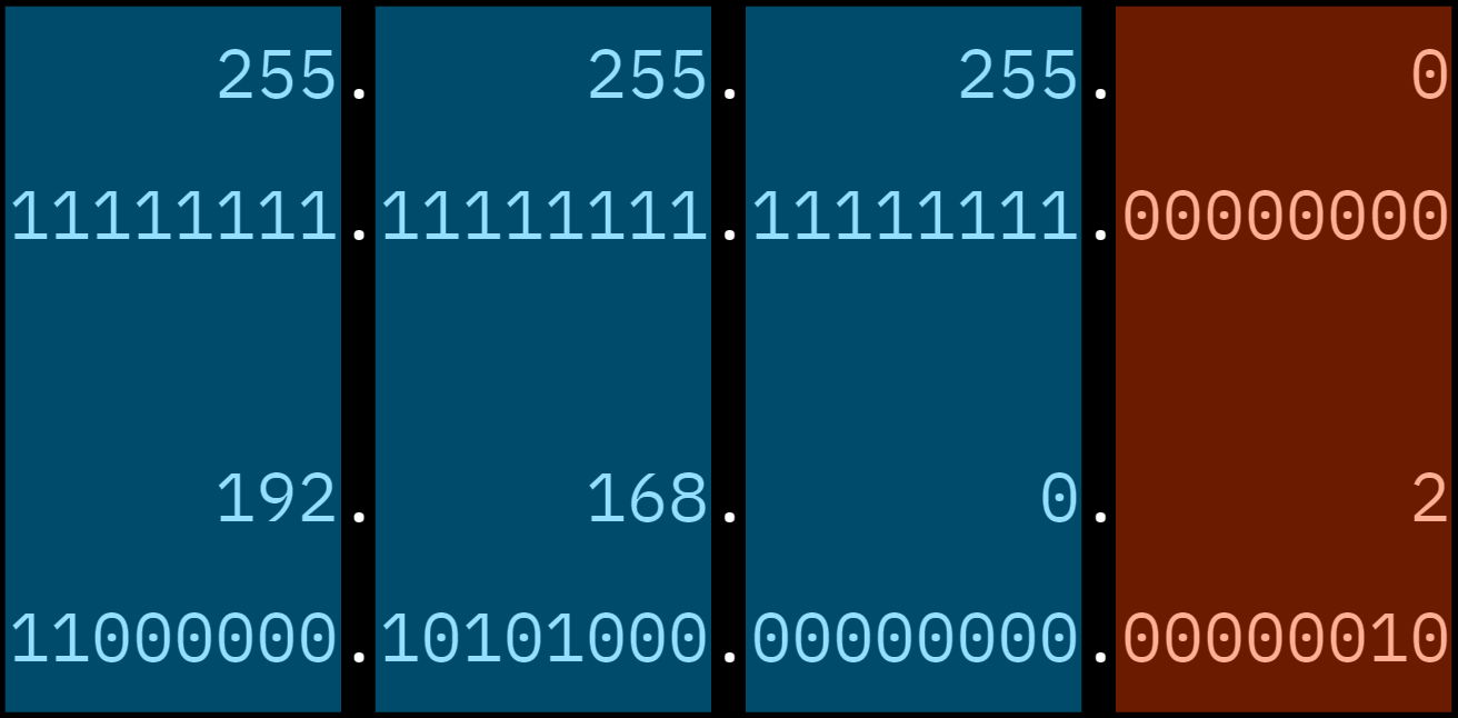 It’s not necessary that “blue” and “brown” digits are split exactly where the dot is, by the way
The bits of the IP address that are placed under the 1s of the subnet mask are called a network number, while the bits that are placed under the 0s are called a host identifier.
The network number is a prefix that all the IP addresses of that network have. In our case, all nodes of the network are starting with 192.168.0. The only changing part of the addresses is the last octet — the host identifier.
The ability to calculate a common prefix for the current network is a superpower of subnet masks. This calculation works with any IP address of the current network. At the same time, network size “tuning” is pretty easy with masks. All you need to do is to add or remove 1s from the mask.
This ability was noticed by the IETF researchers, so in 1993 they introduced the modern way of allocating IP addresses called CIDR — Classless Inter-Domain Routing.
Nowadays, if you administer a subnet, all you need to tell anyone about your subnet is a “network address” and a number of 1s in the subnet mask that is used to define the size of your network. The network address is the first IP address of your network.
E.g. your company owns a network starting with 200.169.0.0 and having a subnet mask equals 255.255.128.0. It means that the first 17 bits of every IP address of the network are a network number, while the last 15 bits are a host identifier. In other words, your company administers IP addresses from 200.169.0.0 to 200.169.127.255 inclusively.
CIDR defines a notation that is more compact than an IP address and a subnet mask. Instead of writing “My network starts with 200.169.0.0 and has a subnet mask 255.255.128.0” you may write “My network is 200.169.0.0/17”. That’s it. The IP before the slash sign is the first IP of the network, the number after the slash sign is the number of 1s in the subnet mask.
This CIDR notation will be useful for us when we start discussing the next protocol related to the CDN — BGP. But for now, you should understand that when your computer wants to send a packet to another computer, it:
- Calculates the network number using its own IP address and a subnet mask.
- If the recipient’s IP address belongs to the current network (according to the network number), your computer wraps an IP packet into an Ethernet frame and sends it directly to the recipient using its MAC address.
- If the recipient’s IP address does not belong to the current network, then your computer does the same thing but sends the frame to the router, not to the recipient directly.
It looks like it’s finally time to check out the IP packet header.
Internet packet header
Here it is:
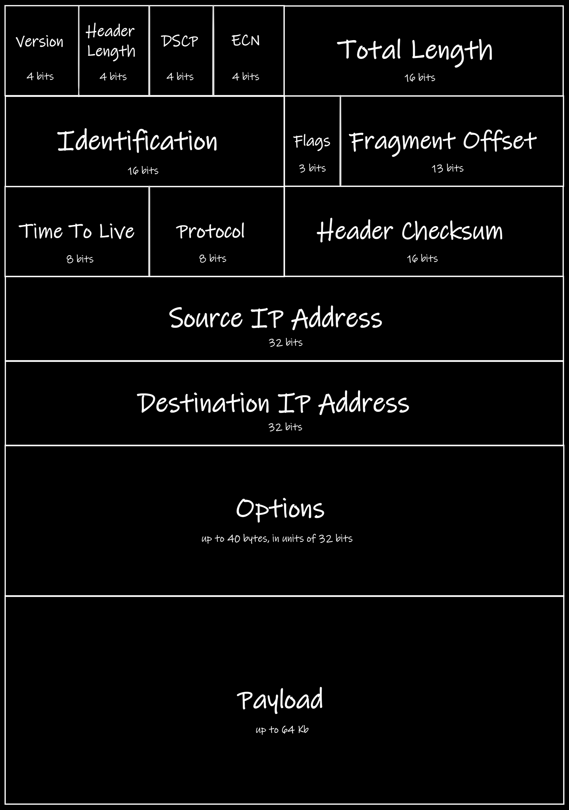 Yeah, there are a lot of stuff
Some of the fields are probably obvious to you: Header Length, Total Length, Header Checksum, Source IP Address, Destination IP Address, Options, and Payload. Others might need an explanation.
The first field is a Version. For IPv4 this value equals 4 of course. There is a list of all the possible values if you are interested in them.
DSCP (Differentiated Services Code Point) and ECN (Explicit Congestion Notification) are kind of nerdy ones. These values are used for the classification of the traffic passed by IP. We are not going to describe them in this article.
IP packets may be split into parts for the easier transmission by lower-level protocols (such as Ethernet). For this purpose there are three fields:
- Identification. This is an ID for the group of packets that should be combined into the whole one.
- Fragment Offset. The place of the current fragment in the whole packet.
- Flags. There are two of them: More Fragments (MF) and Don’t Fragment (DF). The first one means that the current fragment is not the last one. The second tells the intermediate router that it should not fragment the packet at all.
To prevent an infinite packet from passing through the incorrectly configured network, there is a field called Time To Live (TTL). It is not actually the time as we know it. TTL is measured in “hops.” Hop is a pass between two nodes. So, when an intermediate node gets the packet, it decreases TTL by 1. If the value it gets equals 0, the node drops the packet and does not pass it anywhere else.
Finally, there is a field called Protocol. As you might guess, it tells the node, processing the packet, what upper-level protocol has used IP to transmit its data. There are more than a hundred protocols that may use IP, by the way.
Summary
Now you know what an IP packet looks like, what the purposes of IP addresses and subnet masks are. You also know how subnetting works and what CIDR is.
What you probably don’t know right now is how the packet actually goes through the network from you to Google. What is the use of IP there? How do routers understand where they should send your packet to pass it to Google?
This is the topic of the next article. Stay tuned.